This website is no longer maintained. Its content may be obsolete. Please visit http://home.cern for current CERN information.
Real Time RMS prototype
[for discussion!]
As has been established, there will be a number of real-time processes in
action, including real-time feed-forward of corrections based on measurements
coming from the reference magnets. Inter-system dependencies, settings management,
common requirements for access to various parameters strongly suggest a common
approach. Indeed central control for a given class of correctors to take care
of: summing trims from different inputs, field to current calculation and
hysteresis loop crossing would appear to mandatory.
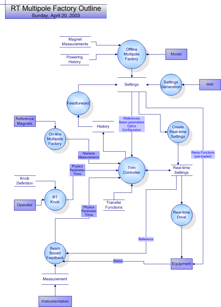
The logical architecture shown below is not aimed the feedback loops
themselves, but at providing common facilities for changing beam and/or magnet
parameters.
Assumptions & Questions
Power Converters
- Single point of RT entry into power converters
- System will allow for RT input for a given corrector from more than one
point of control, possibly but not necessarily, simultaneously. Summing is
therefore done centrally.
- Power converters can execute pre-loaded functions. Could drive correctors
during injection? Will drive them during the ramp.
Magnets
- Control of corrector settings, translation between high level parameters
and current for a given class of correctors needs to be performed at a
single place. That is, strength to gradient conversion, the transfer
function look up, taking care of hysteresis loop crossing etc. Changes in
the correctors can be tracked and appropriate adjustments applied as
required. This process will require access to the transfer functions and
beam parameters (such as energy).
- Open question: Do real-time measurements from reference magnets come in as absolute
values? What is input? How?
- A "current forecast" model: this would look at the multipole history of the reference magnets,
and the powering history (in terms of I and T) of the main dipole chains,
and predict the multipole behaviour of the main magnets. This "current forecast" could be used:
1. at pre-injection to anticipate the magnitude of the persistent currents
at the start of the injection plateau and subsequent decay on the injection
plateau.
2. just before the start of ramp to anticipate the depth of the snapback,
given the adjustments made on the injection plateau, the measured
chromaticity, and length of time on plateau.
Beam Measurements
- Chromaticity feedback not available routinely.
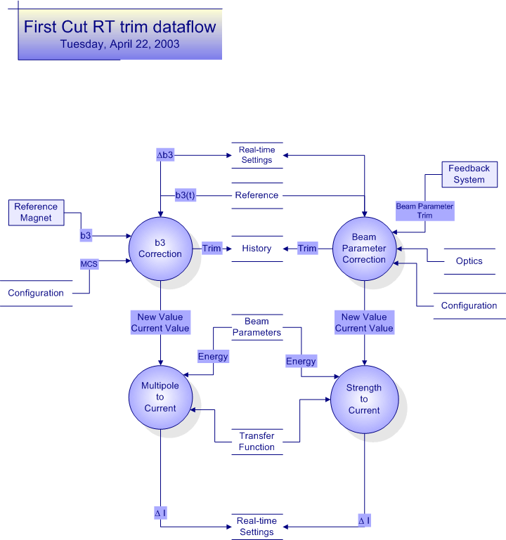
Possible nominal sequence for handling b3
- Pre-injection: The off-line MF model produces prediction of persistent
current and their decay. Predicted b3 behaviour written to database. If
different enough from last fill, prediction converted into time dependant
corrector functions and downloaded to power converters. Possibility to
incorporate empirical trims to predicted corrections established from
experience.
- Ramp to injection level
- Timing event to power converters which start driving correctors with
pre-loaded functions.
- Enable reference magnets, which feed measurements to MF-RT feed- forward
process. The latter compares with respect to reference and produces
correction if necessary.
- Inject pilot
- Measure chromaticity, correct with main sextupoles.
- Before ramp, assuming random length at injection: call MF model to make
prediction about snapback depth/b3 behaviour (and other multipoles), produce
corrector functions. Stop power converters executing injection plateau
functions. Load power converters with ramp functions, start ramp. MF-RT feed-forward
clearly has to be kept carefully informed about reference values during this
phase (if it needs to be on).
Prototype
Within agreed framework:
- First model to produce predicted persistent current and decay. Need to
decide what parameters will be exchanged.
- Convert to correction functions.
- Download to power converter.
- Dummy up reference magnet to provide RT multipole measurement.
- Compare with reference. Compute correction. Compute current change. Feed
to power converter.
- Try running the two together!
- Offline model to produce predicted snapback behaviour. Start ramp. Test
RT-MF b3 to current plus
hysteresis loop crossing.
Data Flow
Trim Controller (e.g. b3 and feedback)